SCARA Dual Parallel Arm Robot
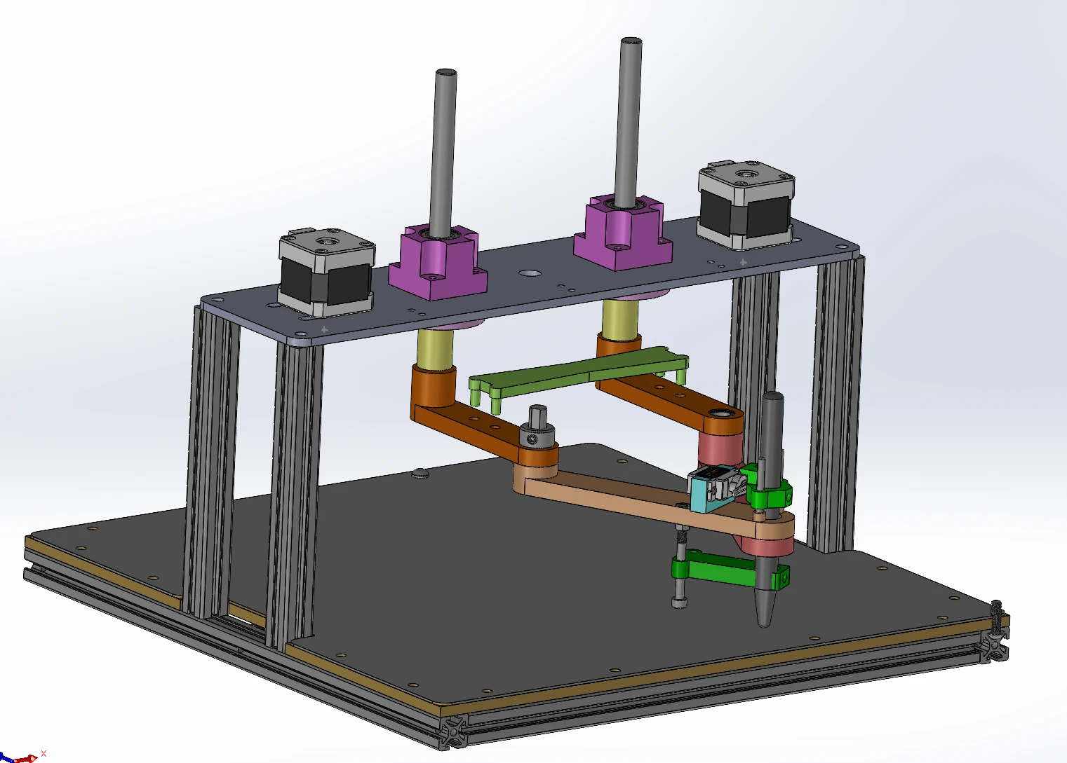
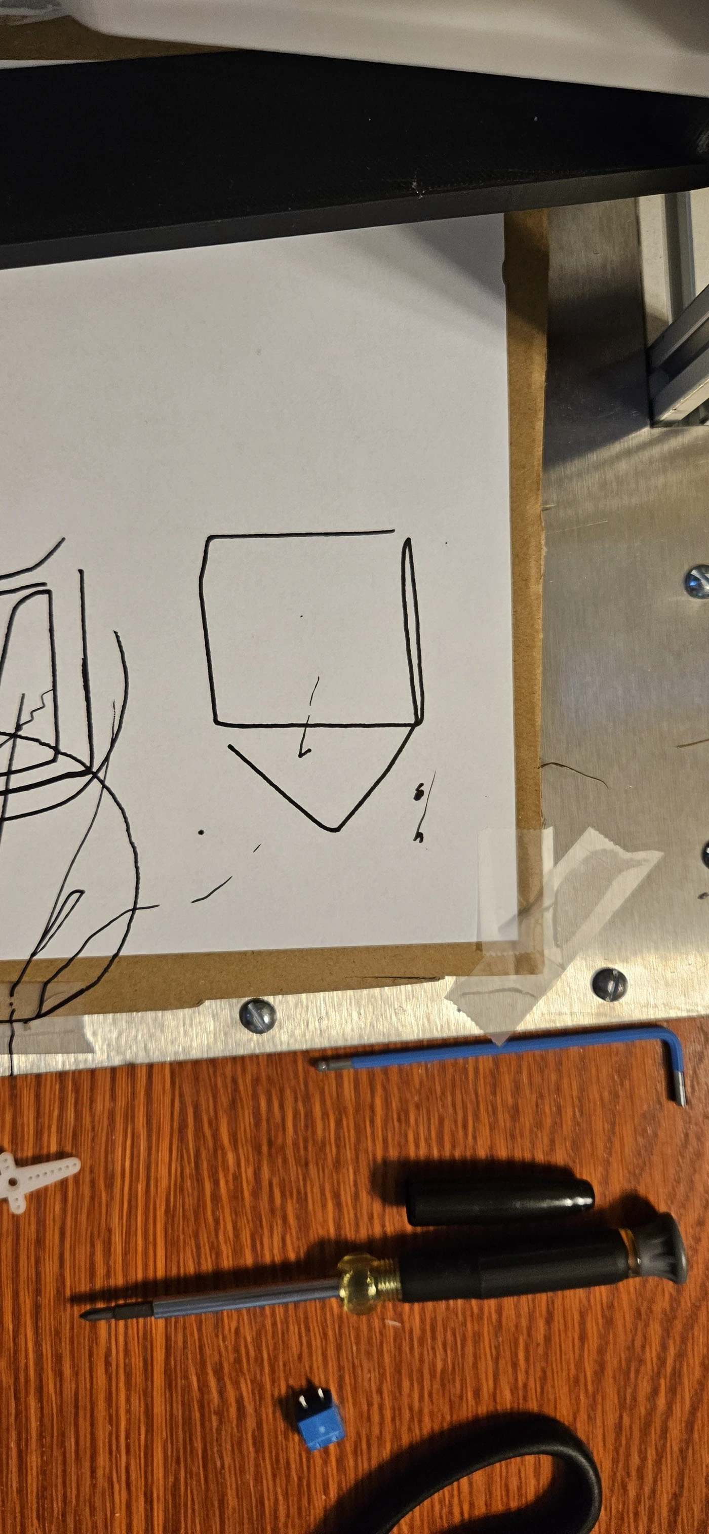
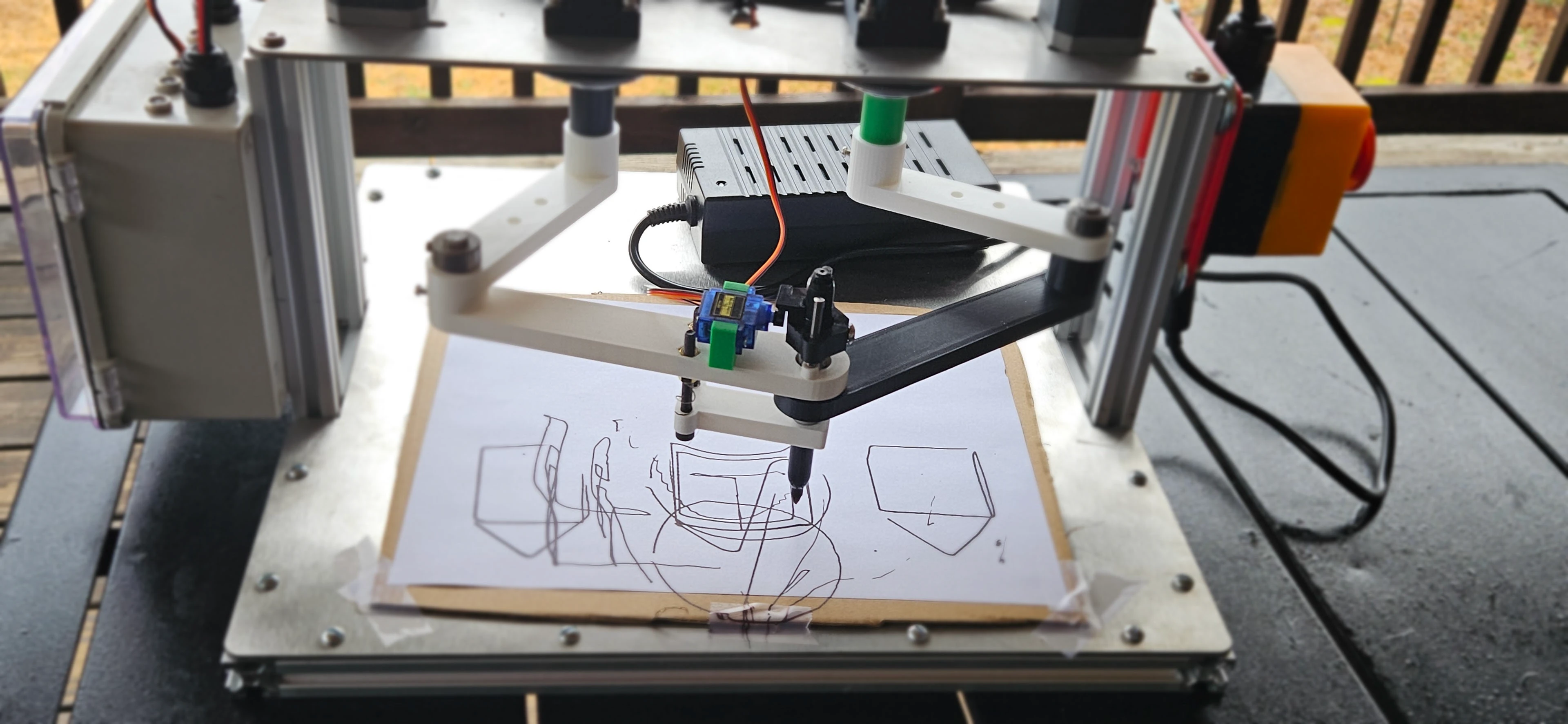
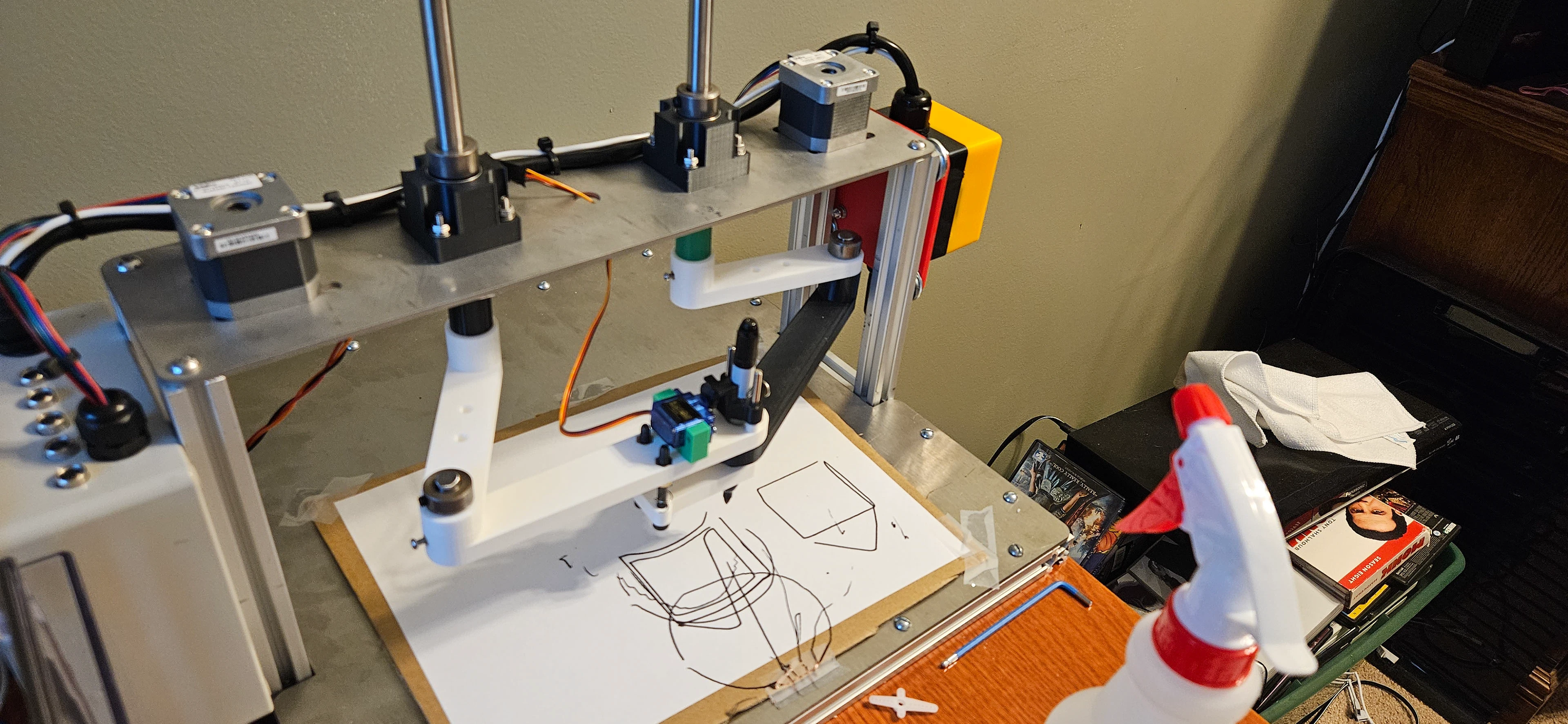
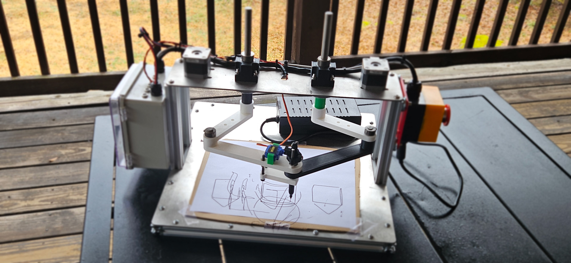
A dual-arm parallel SCARA pen plotter built from scratch, driven by hand-derived inverse kinematics.
Solo build · Fall 2025 – January 2026 · Team of 1 · 9 key work items · 9 evidence-backed
What I owned
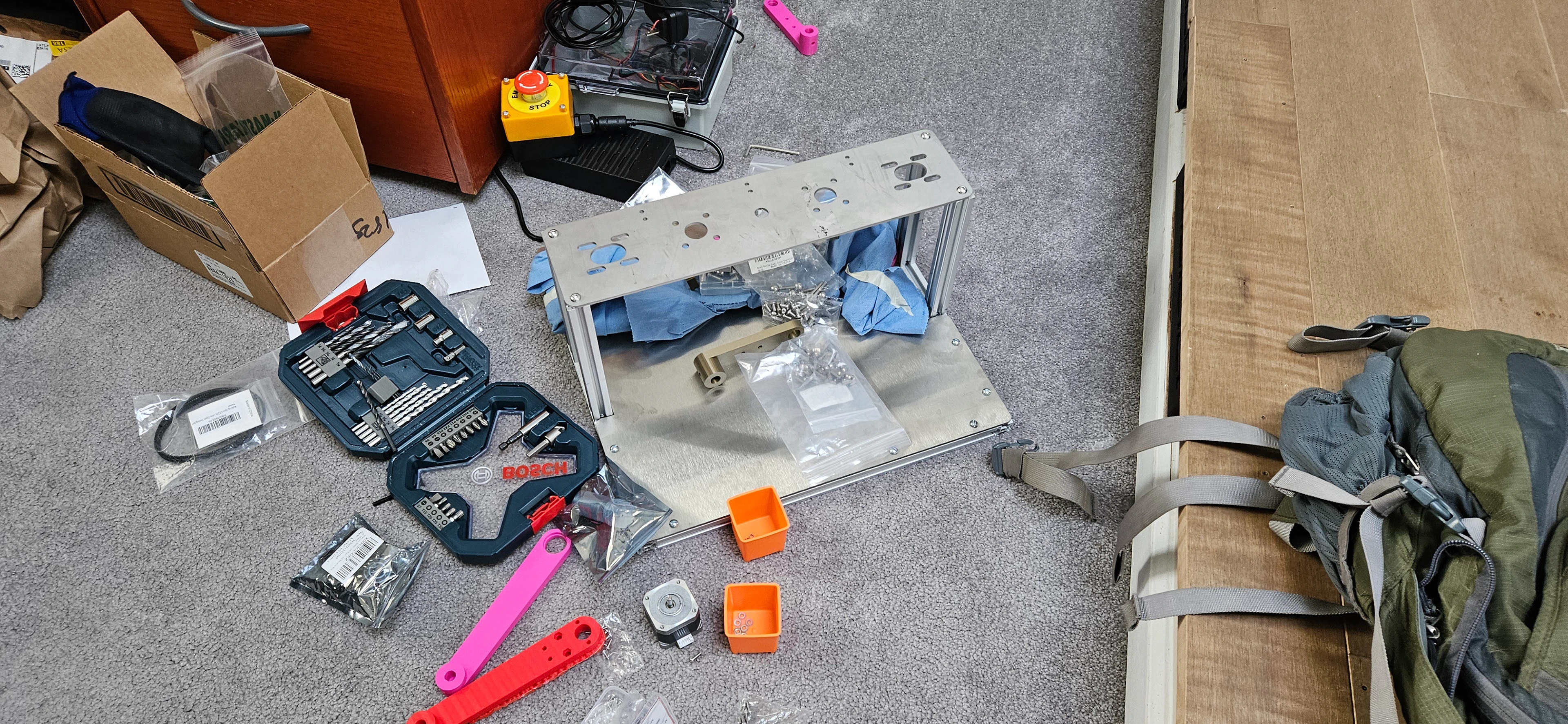
I designed the mechanical and electrical systems in SolidWorks and Cirkit Designer, cut and machined the aluminum extrusion frame, assembled the belt drive train, built and debugged the stepper driver electronics, and derived the forward and inverse kinematics by hand before implementing them in Python and Arduino.
Key Work · 9
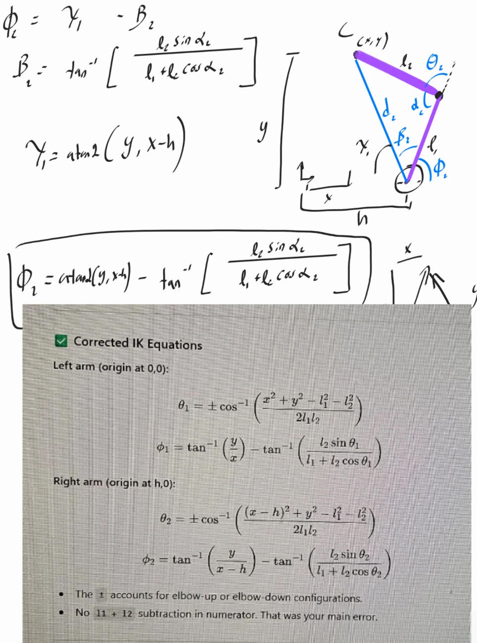
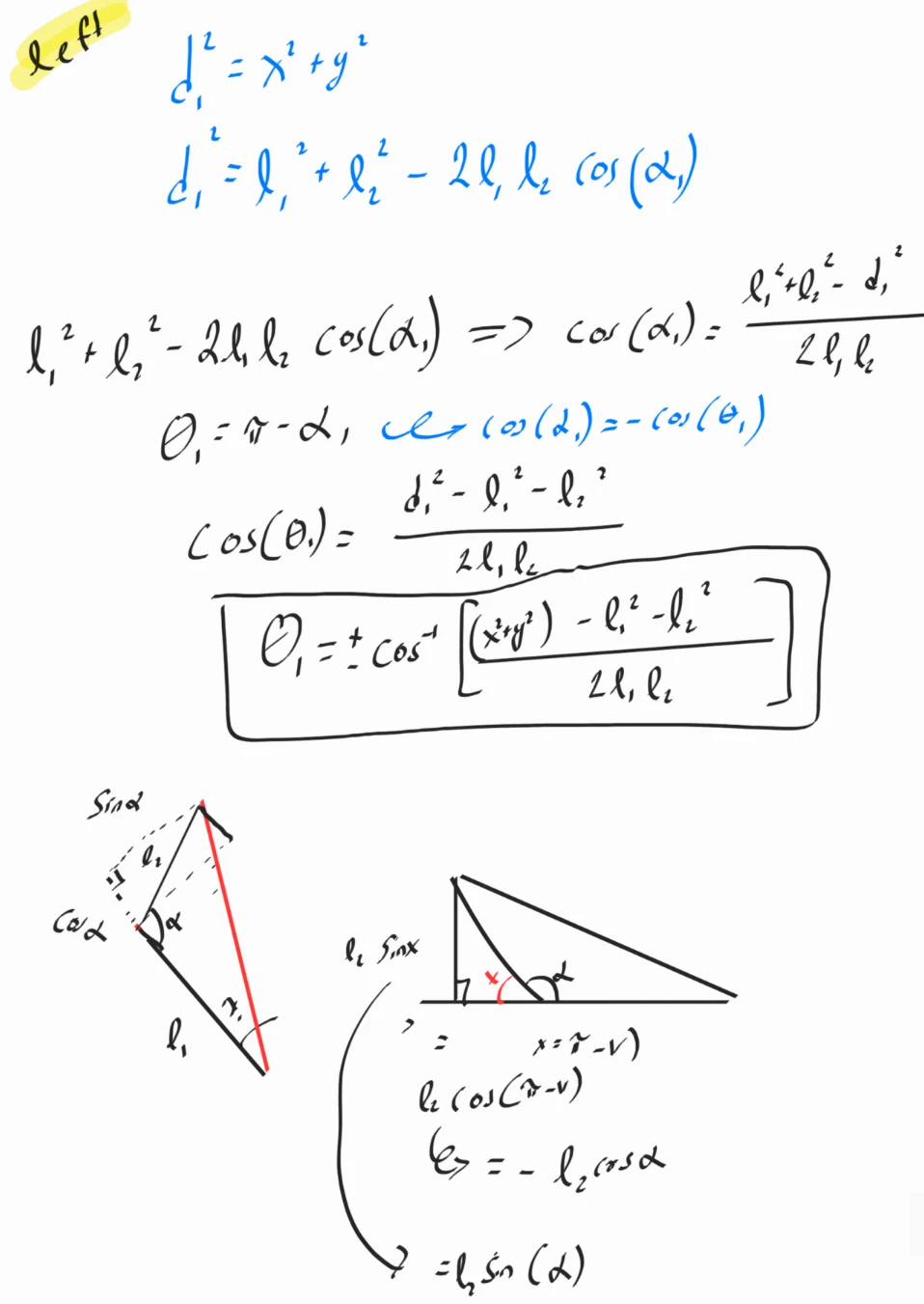
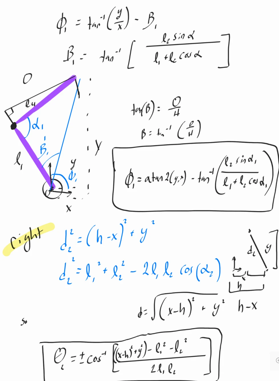
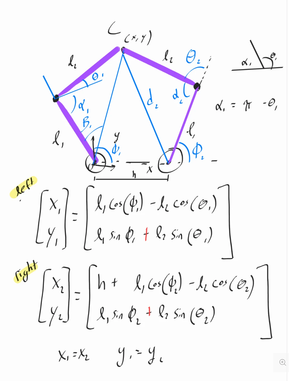
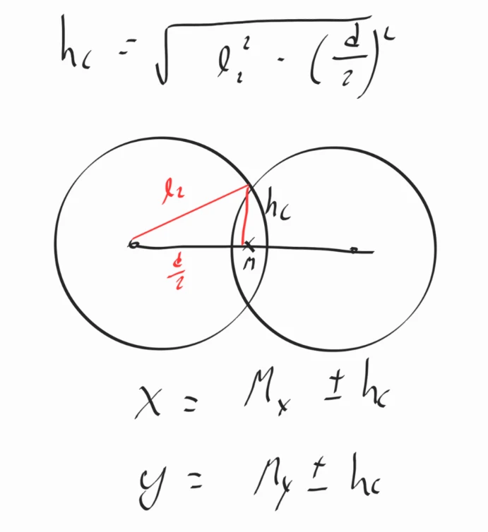
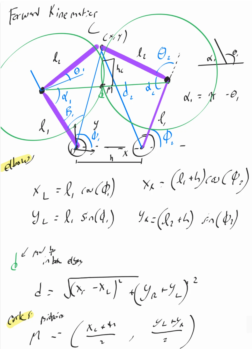
Derived forward and inverse kinematics for a parallel five-bar linkage
▾System successfully produced correct motion after adjustments.
Abandoned the cam-and-spring pen mechanism after clearance forced the pen rearward
▾Moving the pen rearward increased the moment about the sliding points enough that friction stopped the carriage moving freely. Mechanism abandoned.
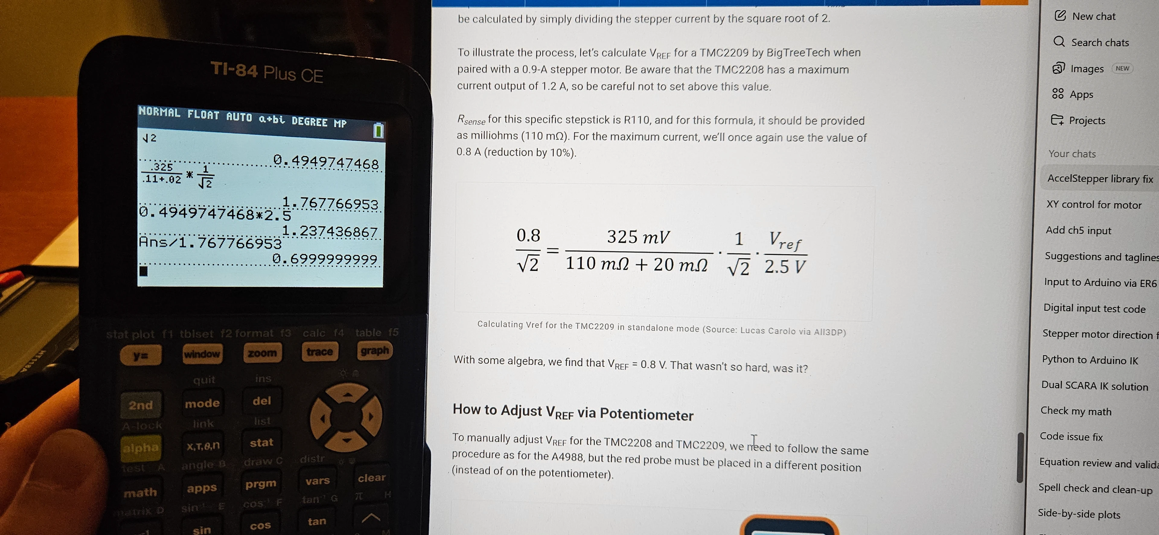
Calculated and set the stepper driver current limit from the TMC2209 formula
▾Drivers ran safely and reliably afterward.
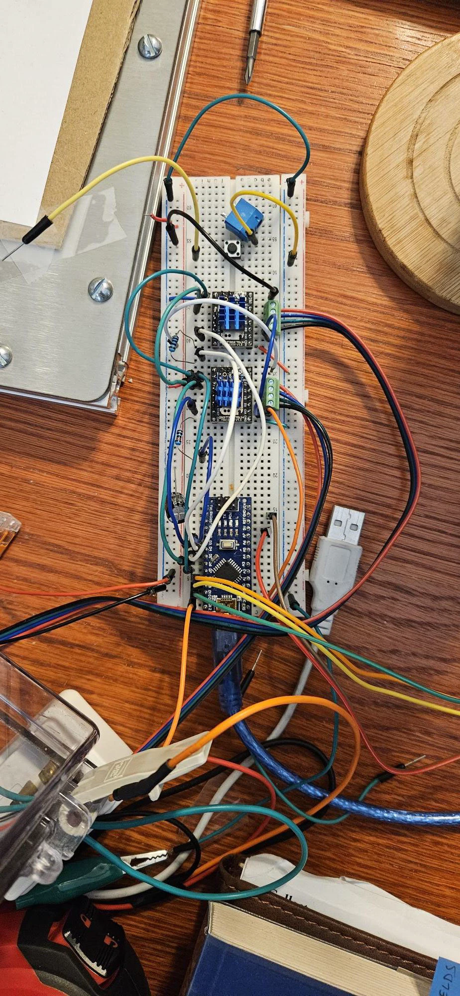
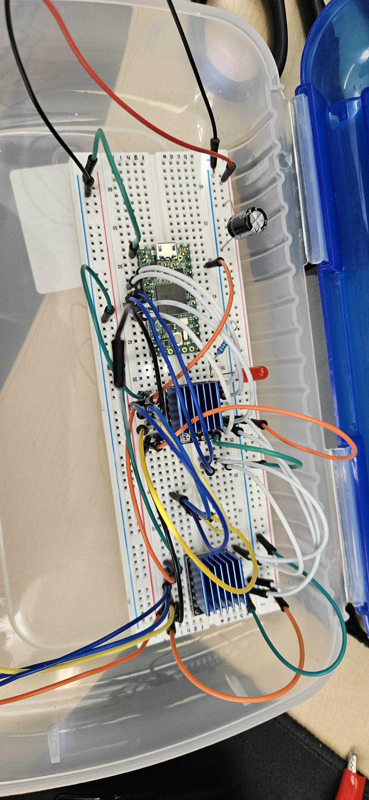
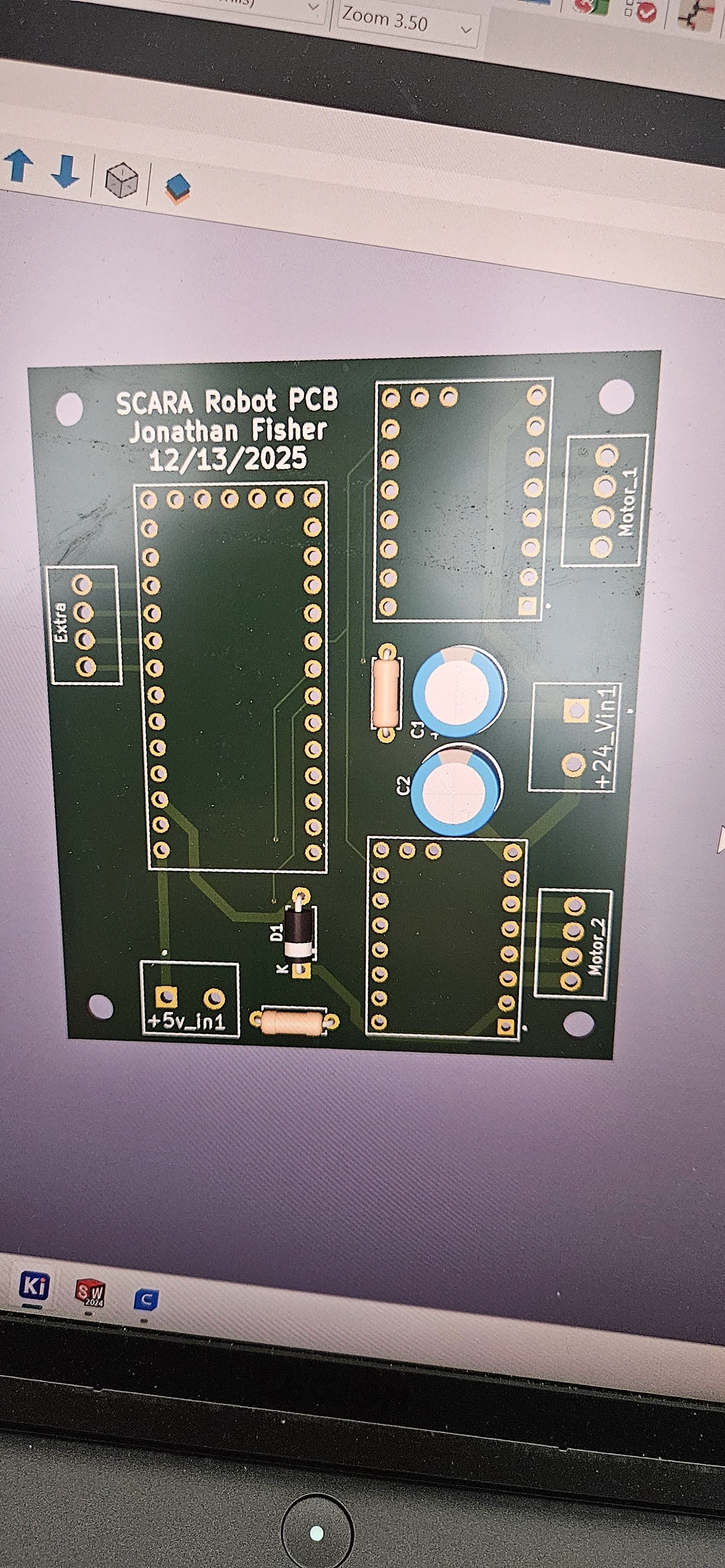
Fell back to an Arduino Nano after damaging the Teensy, retiring the custom PCB
▾Arduino Nano functioned reliably and the robot reached a workable final state.
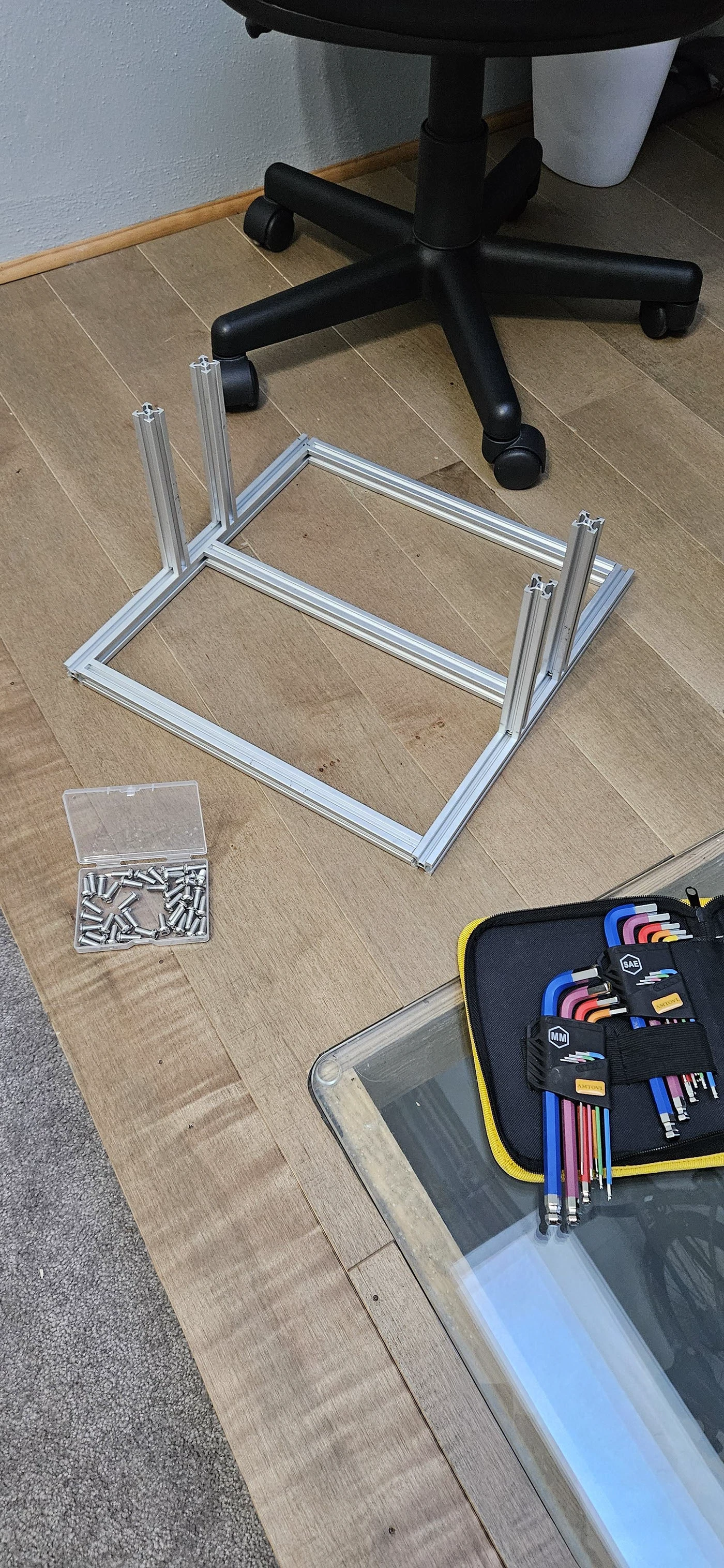
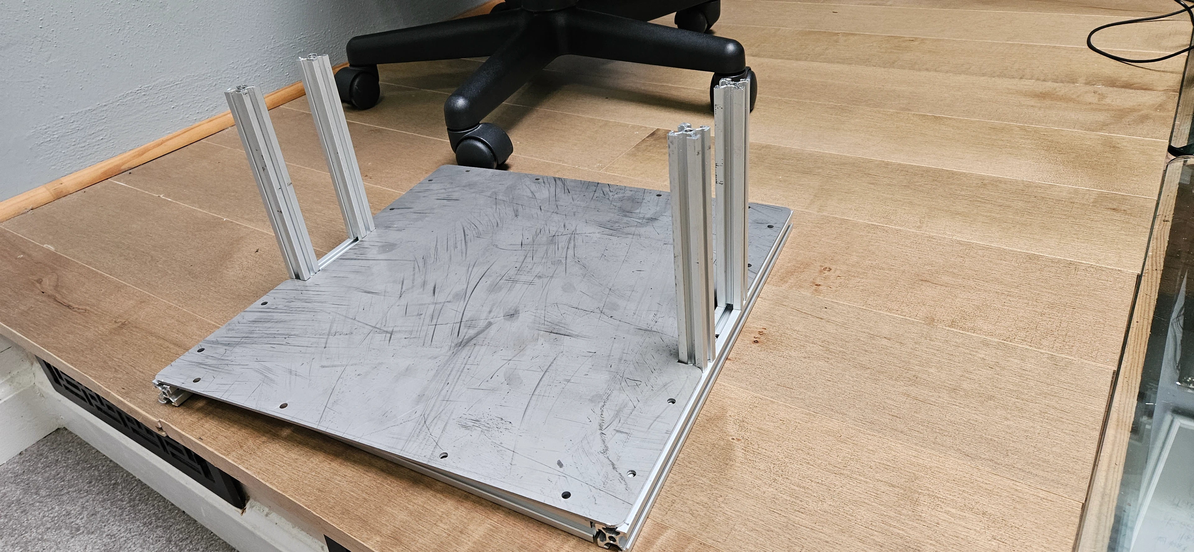
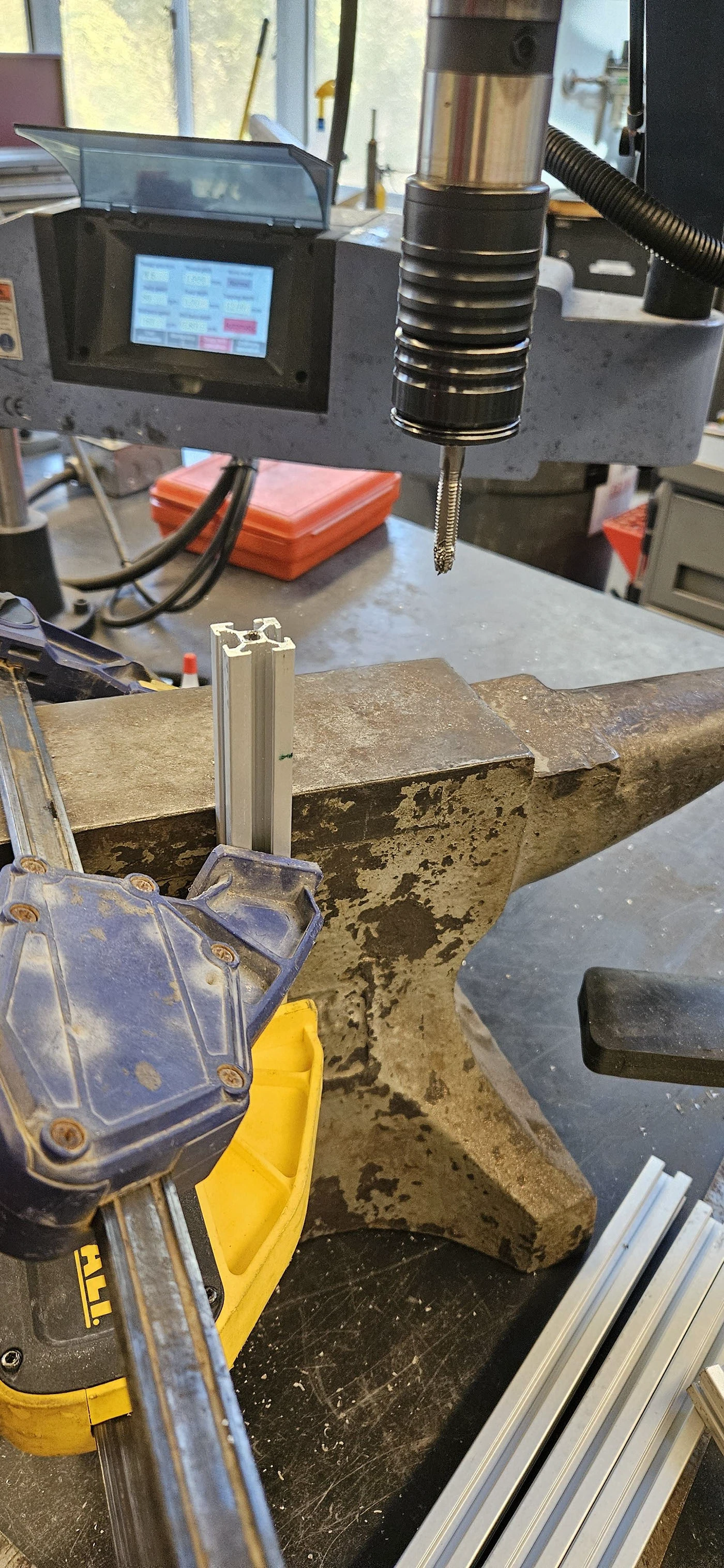
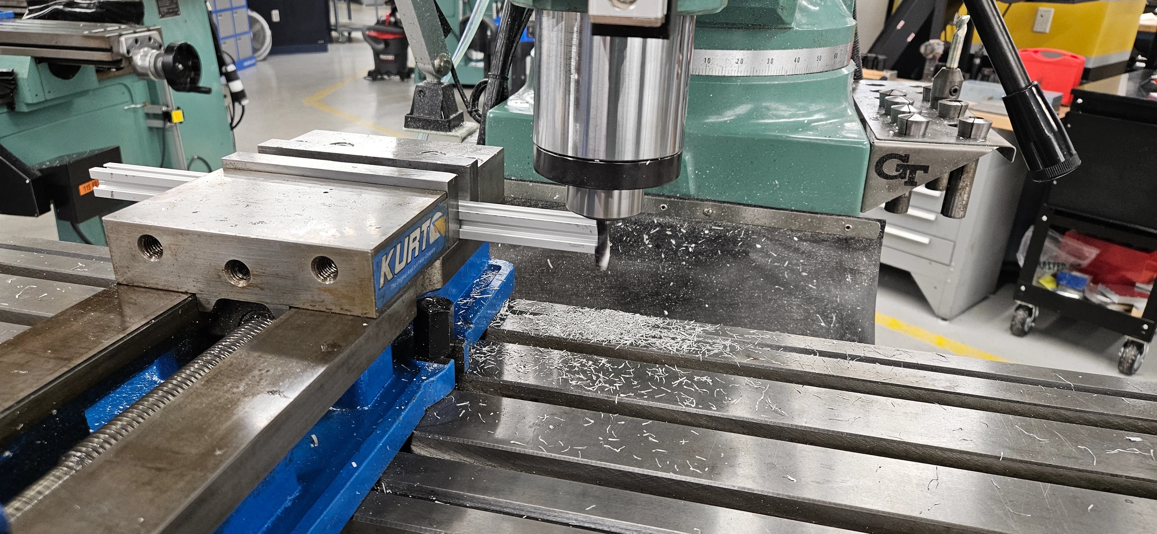
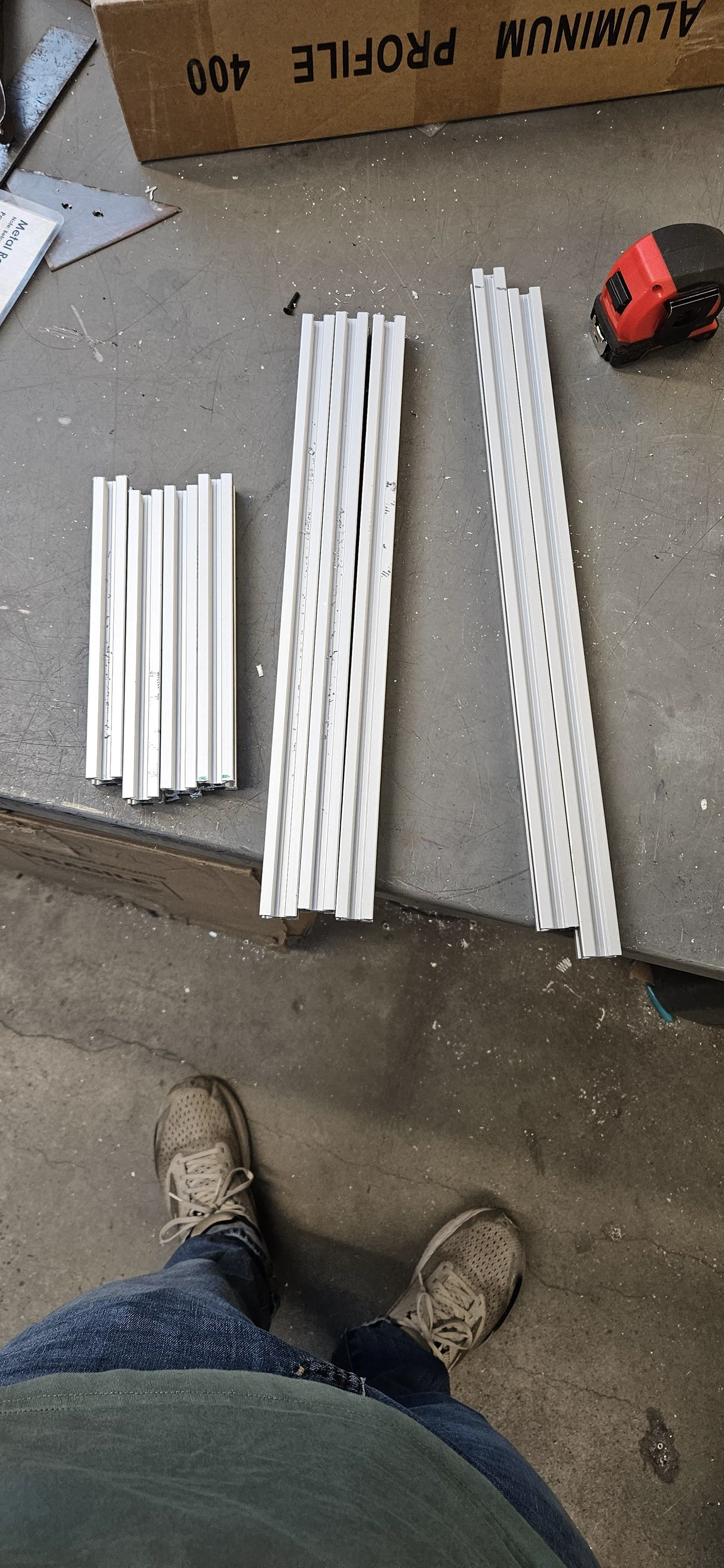
Fabricated the aluminum extrusion frame across four processes
▾Not stated
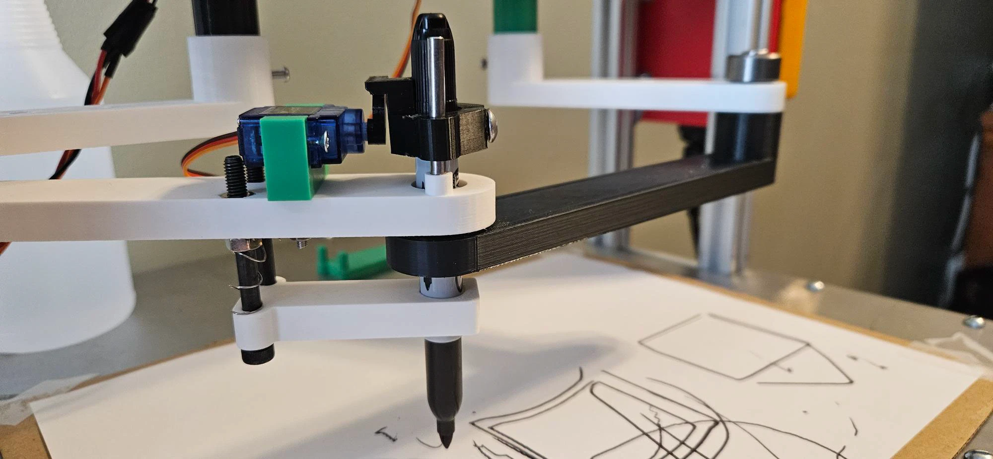
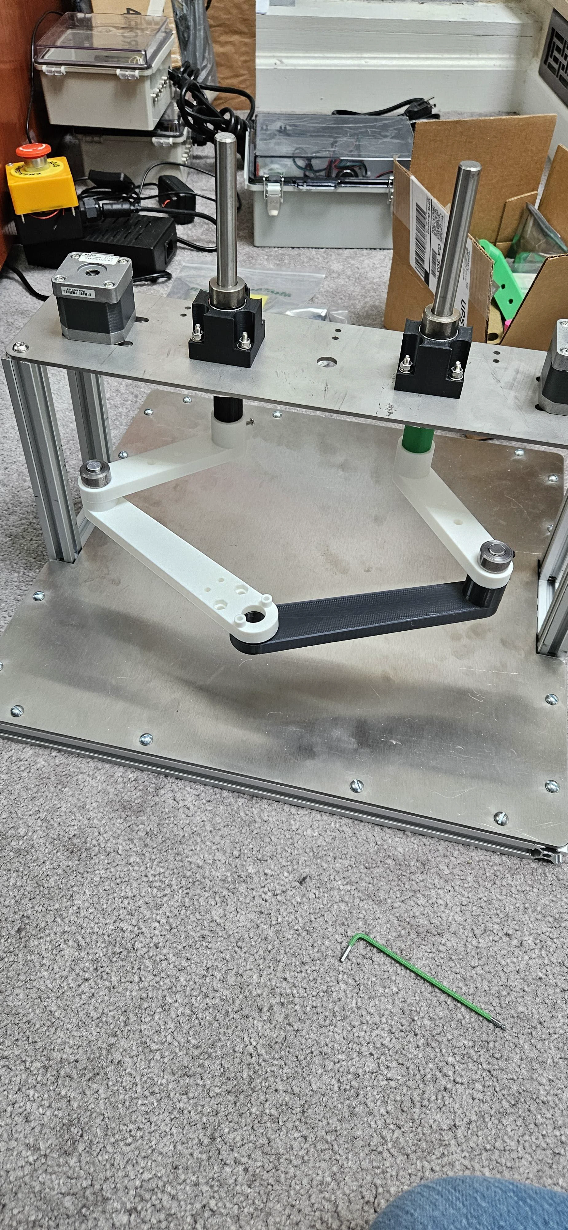
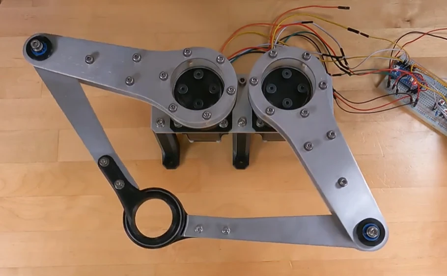
Iterated 3D-printed arms to a working tolerance
▾More than 20 different arm prints before the final version. Finished arms fit together correctly and glide smoothly during operation.
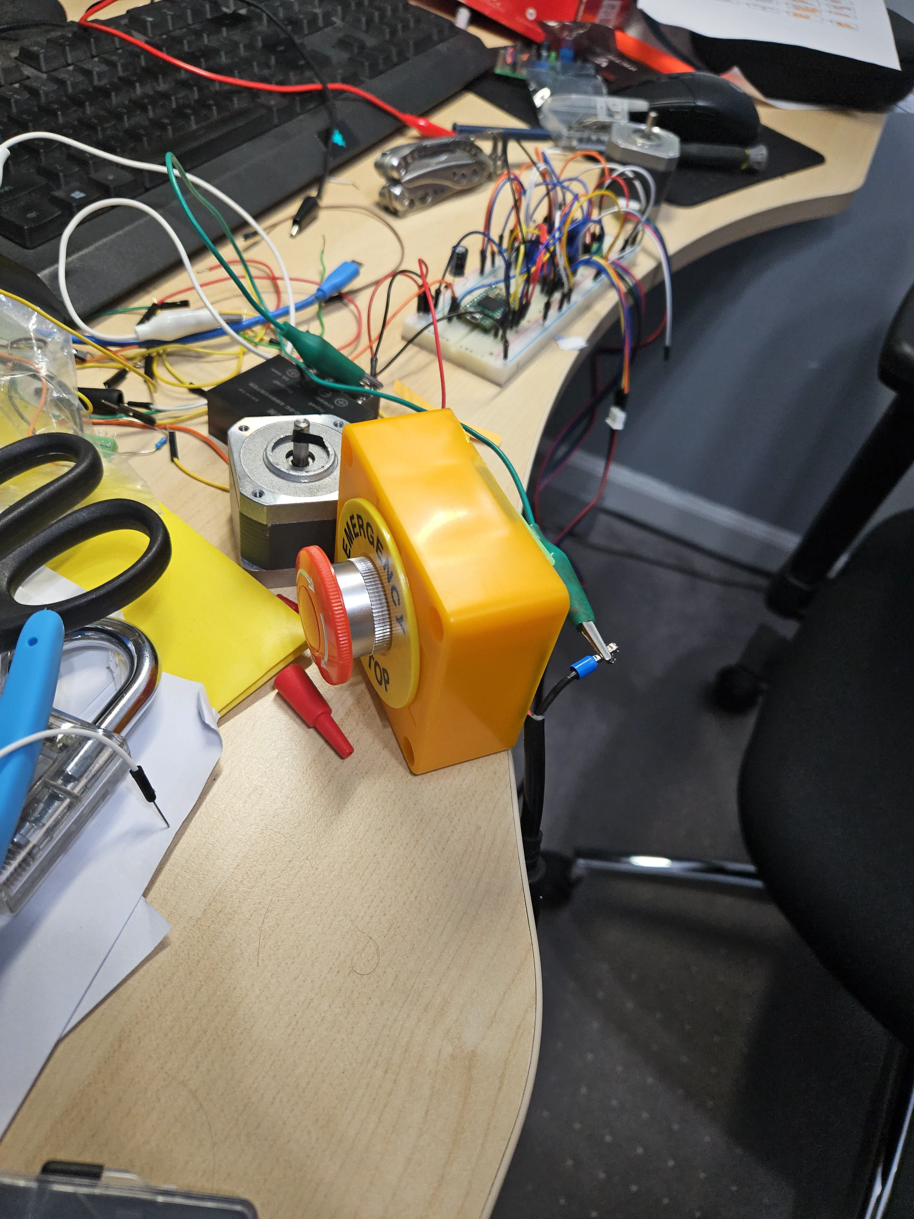
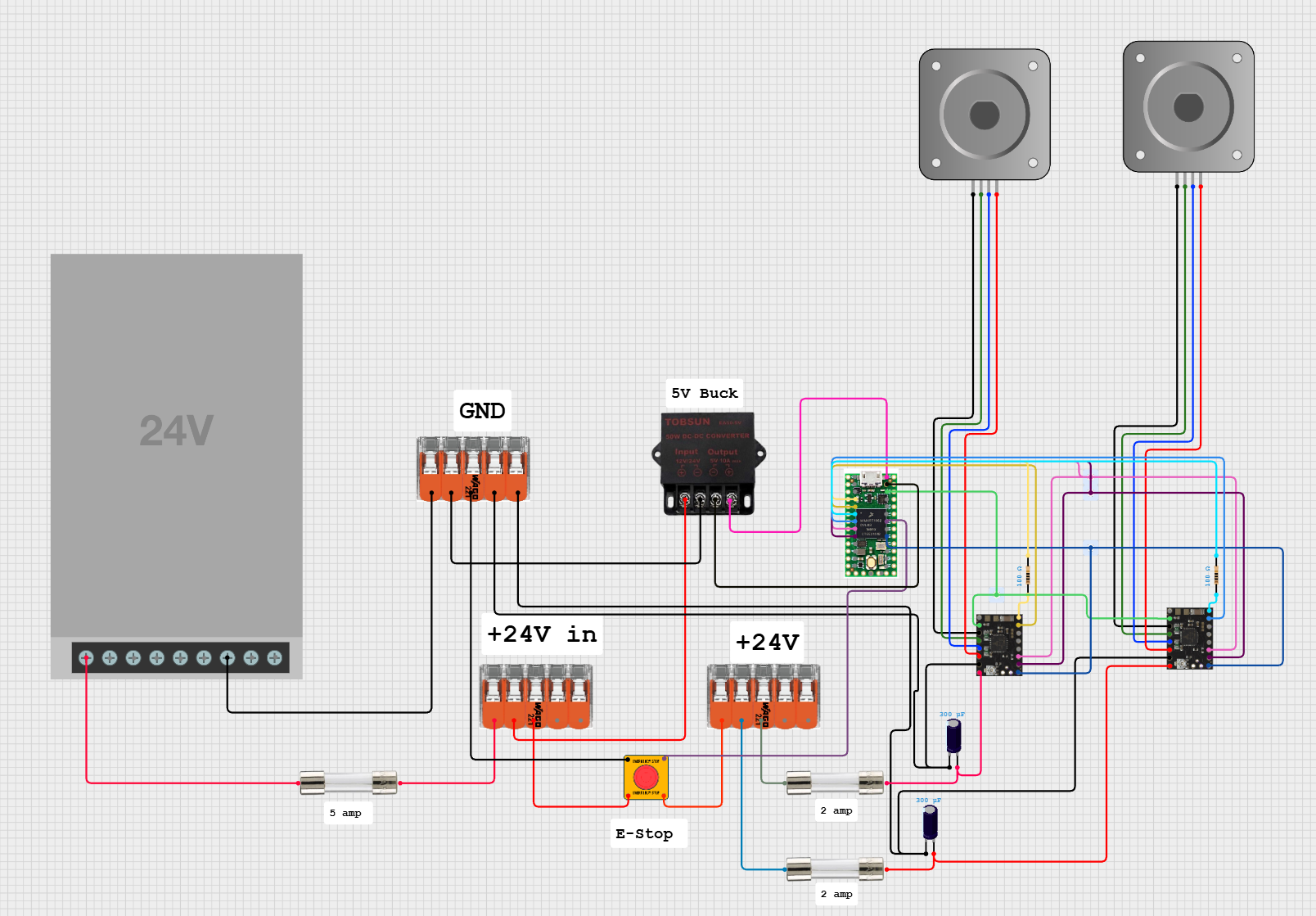
Wired the emergency stop to cut motor power while keeping control logic alive
▾Not stated
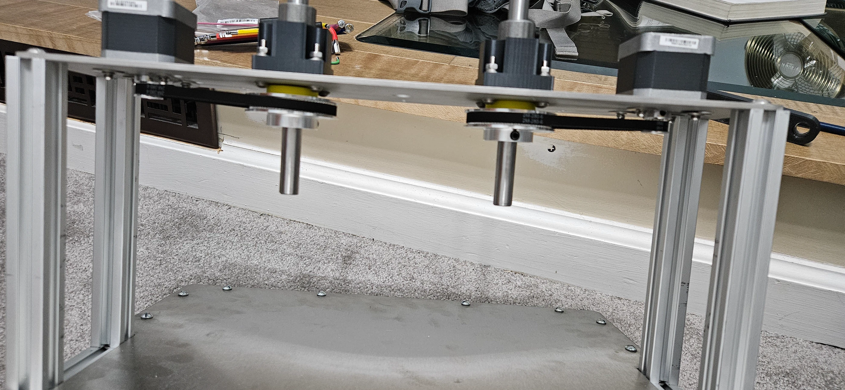
Built the belt-driven drive train
▾Pulleys and belts fit correctly on assembly; the smoothest part of the build.
Planned the electrical system around a 24 V supply with a split 5 V logic rail
▾Not stated
Interfaces
| From | To | Type | Description |
|---|---|---|---|
| Stepper motor | Output Shaft | mechanical | Belt and pulley drive with shaft collars locating the assembly. |
| Output shaft | Top plate | mechanical | Shaft passes through a bearing block bolted to the plate. |
| Extrusion bar end | Frame upright | mechanical | Ends squared on the mill and tapped, then through-bolted. |
| Teensy 4.0 | TMC2209 drivers | electrical | Step and direction control from the microcontroller to both drivers. |
| Servo | Pen carriage | mechanical | Servo raises and lowers the pen at the end of the arm. |
| 24 V supply | 5 V logic rail | electrical | Regulated 5 V split off the 24 V supply, upstream of the E-stop. |
Documents
Lessons
- • Manufacturing at this tolerance is not part of the standard curriculum, so most of the learning sat in the gap between design intent and what a process can actually hold.
- • Deriving the forward kinematics first was what made the reference frame of the physical robot correct; without it the kinematic math did not behave as expected.
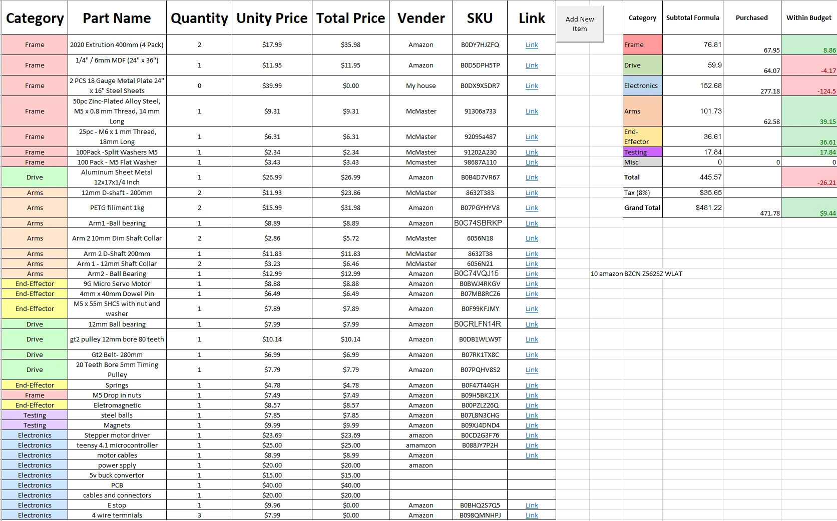
- • Budgeting too little for electronics made me cautious about burning out drivers and microcontrollers, which meant stopping once the machine reached a functional state.